Categories
Blog Code

Designing clean API for AVR round-robin ADC – part 2

I’ve been learning more C++ 11/14 and I initially wanted to build a nice API using variadic templates. When used correctly one can build a clean API with templates that compile down to very small code. Unfortunately AVRGCC does not yet support C++ 11/14 so I can’t follow that route.  Here’s my bullet point summary of the day’s findings:

  • Early template classes experiments messy/confusing.
  • C++0x14 does not work on AVR right now anyway.
  • Linked lists simply don’t optimise away.
  • Virtual methods don’t optimise away.
  • Best approach seems to be general class.
  • Static functions in a namespace compile even smaller than class.

My strategy here was to start with a nice OOP design and rapidly iterate ideas using Compiler Explorer to see where it took me.  I built with AVR gcc 4.5.3 with the flags -Winvalid-pch -Wall -Wno-long-long -pedantic -Os -ggdb -gstabs -mmcu=atmega328p -fdata-sections -ffunction-sections -fsigned-char

Test 1 : Linked lists

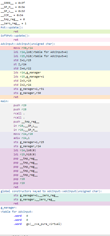
My starting point was a singly linked list of AdcInputs. The AdcManager polling the next via interrupt whilst traversing the list. The derived classes would present a nice API.

adcinput

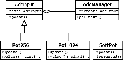
Given my code sample I was hoping the compiler would be clever enough to optimise a lot away, but I am storing data in virtual classes so there’s a lot of vtable setup, calls and the pointers in the linked list are still used in code:

adcinputtest1

Tests 2 – (n-1) : No man’s land

Here’s where it gets a bit messy going through my notes because I didn’t keep copies of all of my in-progress code. In summary I realised that virtual classes and linked lists were not the way to go and experimented with template magic and functors before settling on a simple solution of a central do-it-all manager class.

The problem was making a reasonably friendly access interface out of it. For my applications there are only a few variations on the types of ADC interface, they mostly store a uint8_t as the value – with the edge case of using 10 bit resolution – so would it be possible to cram all the other data into another byte? I could use say 2 bits to store the type of interface and the remaining 6 could be used by each interface’s implementation. For example, storing a ‘pushed’ state for a SoftPot.  In total that gives me a standard 2 byte struct for each interface which I can simply store in an array for the manager.

The bit wrangling ideas came strongly from this hybrid data structures video. They use a heavily templatized method to access bits whilst remaining robust enough to avoid memory stamping.  I’d like to that more in future but for now I’m just using plain old bit fields.

Swapping out the linked lists for a fixed array adds memory overhead because that chunk of memory is always used. However I select AVR chips based on spec; if I only need 3 inputs then I look for the closest match chip rather than an overspecced AtMega328.

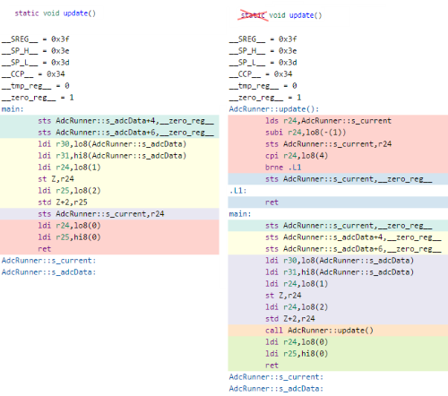
This code is an experiment during this stage.  It’s not pretty but I’m sharing it because it helped me realise the value of using static correctly in optimisation. Here’s what happens when you remove the static keyword from AdcRunner::update():

adcinputtest2

Test 3 : template accessors

With the manager ‘class’ now simply being a bunch of static functions, I’m using a templatized base class to give the user access to each one. Here’s the core class. ADC_TYPE is an enum that defines my fixed set of ADC interfaces. The interface stores a reference to data which is handled by the manager. The idea is as a client you use these objects on the stack merely as accessors to the manager’s data, and that the manager uses these objects to update its data correctly.

template <Type ADC_TYPE>
class AdcInput
{
public:
  AdcInput(Data& data) : m_data(data) { }
  static Type getType()        { return ADC_TYPE; }
  static uint8_t getTypeBits() { return (uint8_t)getType() & 0x03; }
protected:
  Data& m_data;
};

Here’s an example concrete implementation softpot input.  It has accessors for getting the value and determining if it is pressed.  The update method will be called from the manager, it’s a bit ugly but it’s in progress.

class Softpot : public AdcInput<kSoftPot>
{
public:
  Softpot(Data& data) : AdcInput(data) { }
  uint8_t getValue()   { return m_data.value; }
  bool isPressed()     { return (m_data.info & (1 << 4)) != 0; }
  void adcUpdate(); // TBC... this is how the manager updates this data
};

Here’s some code to get a feel for the API

  init_adc();
  add_adc<Pot>(0);
  add_adc<Softpot>(1);
  
  Pot p1 = get_adc<Pot>(0);
  Softpot p2 = get_adc<Softpot>(1);

  for (;;)
  {
    uint8_t val = 0;
    if (p2.isPressed())
      val = p1.getValue() + p2.getValue();
    else
      val = p1.getValue() - p2.getValue();
  }


adcinputtest3

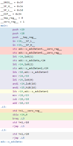
The full version of the test code and compiled output is here and the generated output is on the right.

The current problem with this is that there is no fail-safe on getting the wrong type of object. For example in the above code I have a pot on 0 and a softpot on 1, but there is nothing stopping me trying to read 0 as a softpot. This is not the right place to use exception handling. One option is to store a block of clearly invalid data like 0xFFFF, which you can pick up in debug, but it irks me.

Next step is to try this in action on the AVR and look at the generated assembler with the interrupt handler in place. I have no doubt it will be a little bit longer than writing the code in plain C but I wanted to experiment with something more scalable, and I’ve learned a few things on the way hence this blog post.

Also learned today

  • Today I needed a nice UML editor so I turned to Stack Overflow for advice.  I initially tried Umler, then ArgoUML because I like the developers but it’s a real fiddle (no cut/paste/undo!) so I went Dia which immediately felt nice.  Also jogged my UML memory with this guide.
  • It’s hard to keep blog posts short. Bear with me on this, I’m learning the ropes!
Categories
Blog Code

Designing clean API for AVR round-robin ADC – part 1

softpot
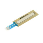
Several of my recent 8 bit microcontroller projects need multiple analogue inputs. I want a nice API that allows me to have different interfaces for getting analogue values, for example reading a straightforward pot as 0-255 or 0-1023, or a SoftPot membrane potentiometer where I may also want to track whether or not it’s
currently pressed.

adc_simple

Reading analogue inputs on AVR chips takes time and the lazy approach to reading an analogue value is to set up the registers to read a value and simply wait for it to come in.  You do something like this:

    ADMUX |= _BV(MUX0);
    ADMUX |= _BV(ADLAR);
    ADCSRA |= _BV(ADPS1) | _BV(ADPS0) | _BV(ADEN);
    while (ADCSRA & _BV(ADSC));	// !

That while loop is just eating cycles whilst we’re waiting for the ADC to return a result.

adc_interrupt
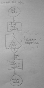
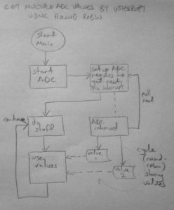
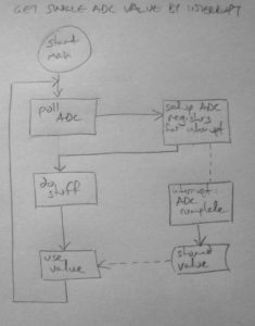
The best way to avoid this wait is to set up the ADC to start reading a value and when it’s ready send an interrupt to get the result.

The interrupt can either use the value immediately or stash it away in a stored value so it can be picked up later on in the main loop.

This approach saves wasting cycles but still has a problem: the ADC can only read one value at a time and I need multiple inputs.

adc_roundrobin

The workaround for this is to make the interrupt run continually and constantly read each ADC value in turn.

The poll requests requests a value for a certain analogue input and when the ADC interrupt is fired off, it re-polls for the next one.  This runs perpetually whilst interrupts are enabled.

The interrupt can act on the values immediately or – if we’re not concerned about keeping everything perfectly in sync – the values can simply be stored in data so it can be picked up in the main thread.

In the next post I’ll explain how I iterated this round-robin in building a fast and clean API for AVR chips.

Categories
Blog

Brain/Project Bootstrap

Since my PhD collapsed I’ve was out of action on the making front. I’ve taken some time to clear my head and now I’m getting the urge to create things again. It’s coming on strong and the problem is when this happens I get dozens of ideas at once, and then I start them all at once, so it all falls apart pretty quickly!

To get past this I’ve resolved to take the path of the the self-indulgent project dev blog. Whatever happens on dev days gets written, the good bits and the bad bits – and there are a lot of bad bits. I’m hoping that this will give me a healthier perspective on ‘failure’ days where I’m going in circles making an API that it turns out I didn’t need, or when I get one of those days where Windows/installers failing seems to waste a whole day *

So for starters, here’s what went well today. I drove up to Nottingham to get myself a signal generator I can gut to make a music interface.  Here’s whats I gots:

marconi-panel

It will anger radio hams that I’m gutting such a beautiful thing but it’s bought more as spares and I’d probably fry myself if I tried to wire it up to the mains. I’m aiming to make this into an exploratory audience-based music interface, largely focused on rhythm. This is exactly the sort of thing my PhD was focused on – dammit – but putting frustrations aside I’m going to just going to build what I can an see where it takes me.

The unit is a Marconi CT452A and it weighs 65lbs. The insides are incredible, I was expecting straightforward vernier potentiometers on the controls but it is heavily mechanical with springs, chains and gears.  I’ve not opened the main electronics section but there are a number of exposed valves and massively enlarged transformer, caps and bridge rectifier.  It’s an old selenium one from General Electric:

marconi-super-diode

So the first part of this project – the pick up – is done. Next I need to strip back the innards and see how easily I can interact with those controls.

What didn’t go so well today was I was planning to do a bit of sight-seeing in Nottingham, but I got there so late I missed the castle. I made it the famous pub ‘Ye Olde Trip To Jerusalem’ though and the contemporary arts gallery, which was typically pretentious, but in the foyer I found an awesome book on Kubrick by Tashen. Actually one good thing there was a dark corridor with sound in the walls, I’d love to have been in a bigger version of it:

dsc_0326

I drove today to ‘Black Box Thinking’ by Matthew Syed on audible, which is part of the motivation for me getting into writing this. It’s really good.  Another good thing was this morning I managed to squeeze one more desk into the workshop which is a hugs win as every other surface is covered in half-finished projects.

* Footnote: on failed APIs and Windows-waste days. I will blog a little about these later because despite being an annoyance it’s wrong to consider them a fail or waste; I learn a lot from these things, the problem is just I don’t write it down anywhere so I forget!  I’ll aim to post about the API experiments tomorrow, it’s an interface for reading Pots and SoftPots on AVRs.

Categories
Blog Code

Self-generating C++ from embedded Ruby

Disclaimer to protect my CV: this is not something I do professionally!

I often need to generate pitch or sample lookup tables for my AVR projects. I usually generate these C++ headers with little ruby scripts.  An evil thought struck me during a long drive… I don’t like these separate little scripts, I want the script inside the header, so if you #include it you get the data, but if you run it with ruby it rebuilds itself.

The thought preoccupied me for the journey.  Preprocessor macros start with a hash, and ruby uses hashes as comments, so you can hide ruby code in a #if 0 block.

The problem was then how to stop ruby from parsing the C++ the file contains. That’s simple enough, you can hide =begin and =end in #if blocks.

The file reading and writing itself is handled using gsub() and some careful regexing. It searches for the tailing end of the table declaration and the hash of the #if that trails it, and the replaces that block with generated values.

Just to be a swine I’ve condensed the Ruby to be borderline unreadable. Save this as ‘notes.h’ and run it through ruby:

#if 0
# Run 'ruby notes.h' and this rebuilds itself.
i=IO.read($0);IO.write($0,i.gsub(/(\]\s=\s{).+?#/m,"\\1 \n #{1024.times.collect{|n|(((44100.0*64.0)/(2.0**(n.to_f/(12*16))*110.0))).to_i}.join(",\n ")}\n};\n#"))
=begin
#endif
uint16_t freq[1024] = {
  25658,
  25565,
  // ... the rest here will be regenerated
  641,
  638
};
#if 0
=end
#endif

Note the regex can’t just search for the ‘] = {‘ verbatim because it would pick up the first instance of that expression in the gsub itself; this code is reading its own text and it would replace the regex! I bypass this by swapping spaces for \s ‘]\s=\s‘.

Here the evil ends.  #include "notes.h" works fine and you can rebuild any time – and risk trashing everything if you have made the tiniest typo :)  Not a good way to approach development but a fun puzzle.  The next challenge is to do this with compile-time table generation using variadic templates.

Categories
Blog Electronics

PipSeq early development

I’ve been off the blog for a while but I have lots of projects on the go and I’m going to have to park some for a few months so this is more a note-to-self so I can catch up in Spring.

I’ve had lots of ideas for rhythmic eurorack modules in mind for a while. I want to create rhythmic frameworks that can be used in live jams, I’m not sure if it’ll work but the modules should be interesting, including lots of the more deeply hooky sounds like polyrhythm and extreme swing. Here’s one in progress called ‘PipSeq’ (or PipSqeq?  Working title anyway):

It’s a minimal sequencer using an AVR but it’ll have a lot of strange features for experimentation.  After this video I was hoping to crack  on with the software to get the polyrhythmic/phasing functionality working but there are a few fundamental hardware issues to sort out first.  I’ve found a better LED driver solution and I want to put decent comparators on the inputs.  On hold for now but watch this space!

Categories
Blog Electronics

Drum machine circuit rework

Latest schematic after trying to reduce distortion in the circuit. I’ve added a volume control, proper biasing of signals from the AtTiny, an active 2-pole filter which gives a really clean output, and a massively minimised output stage which is good enough for testing with headphones. My analogue electronics is hit and miss so these values have been found experimentally.

The volume control is part of the biasing circuit. In previous circuits I was saturating the PWM signal into the op amp causing it to clamp to it’s full possible range. This was great in theory but in practice working at full range caused distortion at the limits; there was noise on the top and flattening out of the signal at low frequencies.

With the circuit operating at 5v the new biased signal going into and coming out of the TL072 is between 1.5v and 3v, giving enough tolerance for a clean signal.  This is enough voltage to drive the transistor directly, so it runs unbaised with a 10k resistor to convert this to a base current. The component values are borrowed from this excellent three transistor headphone amp.

The low pass filter part is taken from this excellent example. It might be cutting off the high frequencies a little too soon but I’ve left this in so the high sounds are not too piercing. The nice part about this configuration is that’s a neat footprint on protoboard/breadboard as the two caps sit neatly right next to the op amp (15nF going left from pin 2, 33nF going right from pin 3). This is more a note-to-self for breadboarding future versions, and also why I’ve drawn the circuit including the chip pinouts.

Also as a note to self is this great PDF on biasing op amps, a ridiculously thorough PDF from Texas Instruments (mostly massively out of my league) and a pinout of the trusty TL072:

tl072


Categories
Blog Electronics

AVR cheap bass drum synthesis

The idea with the drum synth is to get a wide range of sounds out of the smallest, simplest possible circuit. There are 4 drum modes, bass, snare, hat and something more glitchy. I’m using an AtTiny45 as it’s got analogue inputs, fast PWM for output and enough memory for a few lookup tables of data. Here’s the test circuit:

The AtTiny chip is computing each sample at roughly 31kHz so I need to avoid any CPU-hungry operations like multiplication (8Mhz clock/31.25kHz = 256 instructions max). The bass drum gets around this by using two 8 bit lookup tables, each 256 bytes in size. The first is an ‘impact’ table which is a sort of exponential drop off curve and the second is a sine wave scaled to a 0-255 range. Source code is here (Compiled in g++, fuses L = 0xE2, H = 0xDF, E = 0xFF) and here’s the bit that does the important work:

impactPos += speed;
sinePos += pgm_read_byte(&amp;impact_tbl[(impactPos &gt;&gt; 8) &amp; 0xff]);
sample = pgm_read_byte(&amp;sine_tbl[(sinePos &gt;&gt; 4) &amp; 0xff]);

The sine table is being modulated by the ever-decreasing impact table so the frequency drops over time. The speed of the playback determines the pitch of the drum and the initial impactPos determines the type of sound. For a cheesy 70’s disco tom you set it to zero to go from a really high tone down to a low one. For a tech bass you start further down the curve to get a more muted and constrained sound.

This is a lazy approach as there is no decay on the volume – instead it depends on the drum playing out until the frequency of the sine wave is too low to hear. This avoids any multiplications but has some 8 bit artefacts as a consequence (I kind of like them).  Here’s some example output:

[audio:http://www.alexallmont.com/wp-content/uploads/2012/04/AttinyBassDrumTest.mp3|titles=AtTiny Bass Drum Test]
Categories
Blog Electronics

AVR filtered noise

A cheap LSFR gives a simple white noise output:

//--------------------------------------------------------------------------------
// Fast pseudo random number generator from
// http://en.wikipedia.org/wiki/Linear_feedback_shift_register
//--------------------------------------------------------------------------------
uint16_t g_rand = 0xACE1u;
void nextRand()
{
  g_rand = (g_rand &gt;&gt; 1) ^ (-(g_rand &amp; 1u) &amp; 0xB400u);
}

I want the effect of  filter sweeping this but being a little 8 bit chip, proper DSP is out of my league. Instead I do a cheap low pass filter by averaging the last sample with the current one, then the previous one to that with its previous etc.  To get more variation I average every other one and then fill the gaps, generates a sort of noise drop off curve:

#define FILTER_NOISE(idx1, idx2)    g_noise[idx1] = (g_noise[idx1] &gt;&gt; 1) + (g_noise[idx2] &gt;&gt; 1);
#define AVG_NOISE(idx1, idx2, idx3) g_noise[idx1] = (g_noise[idx2] &gt;&gt; 1) + (g_noise[idx3] &gt;&gt; 1);
 
uint8_t g_noise[16];
void updateNoise()
{
  nextRand();
  g_noise[0] = (uint8_t)g_rand; // ** Initial white noise value
  FILTER_NOISE(2, 0)    // Average every other sample to
  FILTER_NOISE(4, 2)    // get more muffled low pass white
  FILTER_NOISE(6, 4)    // noise.
  FILTER_NOISE(8, 6)
  FILTER_NOISE(10, 8)
  FILTER_NOISE(12, 10)  // Last couple of sample are filtering
  FILTER_NOISE(13, 12)  // each sample.
  FILTER_NOISE(14, 13)
  FILTER_NOISE(15, 14)
  AVG_NOISE(1, 0, 2)    // Averate between gaps in filtered
  AVG_NOISE(3, 2, 4)    // samples.
  AVG_NOISE(5, 4, 6)
  AVG_NOISE(7, 6, 8)
  AVG_NOISE(9, 8, 10)
  AVG_NOISE(11, 10, 12)
}

Messy code, but still faster than my awful assembly code version… beaten by GCC’s optimiser once again.  Here’s what it sounds like sweeping over this with a pot:

[audio:http://www.alexallmont.com/wp-content/uploads/2012/04/noise-capture.mp3|titles=noise capture]
Categories
Blog Electronics

Drum synth fast PWM

An update whilst getting the drum synth code together. The output is 8 bit at 31.25kHz, a frequency derived from the 8Mhz clock speed divided by 256 – the number of clock cycles it takes for the PWM ramp to go full cycle.

Interrupt initialisation including analogue input for potentiometers and piezo:

int main(void)
{
  // PWM output on PORTB0 = pin 5.
  DDRB = _BV(0);
 
  // PWM init, 8Mhz / 256 gives 31.25kHz
  TCCR0A =
    _BV(COM0A1) |           // Clear OC0A/OC0B on Compare Match.
    _BV(WGM00) |_BV(WGM01); // Fast PWM, top 0xff, update OCR at bottom.
  TCCR0B = _BV(CS00);       // No prescaling, full 8MHz operation.
  TIMSK = _BV(OCIE0A);      // Timer/Counter0 Output Compare Match A Interrupt Enable
 
  // Analogue init.
  ADCSRA |=
    _BV(ADEN) |              // ADC Enable
    _BV(ADPS1) | _BV(ADPS0); // Div 8 prescaler
 
  // Enable interrupts.
  sei();
 
  // Main loop.
  for (;;)
  {
    // ** Get user input **
  }
}

ISR sample update code, the sample is set as the PWM output, the sample update code sets it for the next time around:

uint8_t g_sample = 0;
ISR(TIM0_COMPA_vect)
{
  // 8 bit playback at 31.25kHz.
  OCR0A = g_sample;
  // ** Sample update code here **
}

Not the most cutting edge audio player, 8 bit and no fast buffering of any kind but good enough for now.  The sample generation code is tricker than expected; using an ATTINY45 means that efficient multiplication is not an option I’m in bit-hacking domain.

Categories
Blog Electronics

First Drum Synth Build

The drum runs from 5v but for project completeness sake I put it in a box with a 9v battery. The leftmost two pots control sound parameters with the third controlling volume. The piezo picks up finger impacts from the outside so you can play the drum by tapping the tin. From left to right the circuit goes: 9v to 5v regulator, ATTINY45 synth (with a header around chip for in-circuit programming), filtering & pre-amp, power amp.

Circuits always seem to end up denser when I actually build them – it was a cram getting all this onto protoboard.  The actual circuit is pretty neat but the rats’ nest of cables is from hooking everything up to switches.  I also had to shoehorn more caps in than expected.  It would have been wiser to choose a bigger box and measure/mark out all the controls rather than faff around with files and a hole-borer, but I  learned a lot for the next build in the process.  Notably: I’ve never experienced dry solder joints before but the analogue stage of this circuit really highlighted them, I’m used to using strip board and not this sort of protoboard so I need a bit of practice here; the piezo does all manner of weird stuff when the metal side is against the inside of the tin, grounding issues; the whole circuit could be shuffled to the right – squeezing the battery in was a relatively last-minute decision.

Paint job required. I’m still running this with the original software from my rhythm piano and I want to add more range to the sounds. The next post will have the first ‘official’ code release in which I’d like to include some lovely abrasive glitchcore modes I discovered whilst this circuit was playing up.