Categories
Blog Electronics

PipSeq early development

I’ve been off the blog for a while but I have lots of projects on the go and I’m going to have to park some for a few months so this is more a note-to-self so I can catch up in Spring.

I’ve had lots of ideas for rhythmic eurorack modules in mind for a while. I want to create rhythmic frameworks that can be used in live jams, I’m not sure if it’ll work but the modules should be interesting, including lots of the more deeply hooky sounds like polyrhythm and extreme swing. Here’s one in progress called ‘PipSeq’ (or PipSqeq?  Working title anyway):

It’s a minimal sequencer using an AVR but it’ll have a lot of strange features for experimentation.  After this video I was hoping to crack  on with the software to get the polyrhythmic/phasing functionality working but there are a few fundamental hardware issues to sort out first.  I’ve found a better LED driver solution and I want to put decent comparators on the inputs.  On hold for now but watch this space!
Categories
Blog Electronics

Drum machine circuit rework

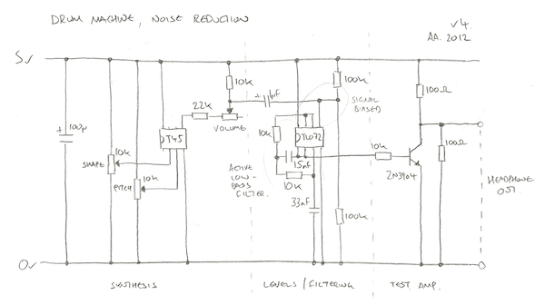
Latest schematic after trying to reduce distortion in the circuit. I’ve added a volume control, proper biasing of signals from the AtTiny, an active 2-pole filter which gives a really clean output, and a massively minimised output stage which is good enough for testing with headphones. My analogue electronics is hit and miss so these values have been found experimentally.

The volume control is part of the biasing circuit. In previous circuits I was saturating the PWM signal into the op amp causing it to clamp to it’s full possible range. This was great in theory but in practice working at full range caused distortion at the limits; there was noise on the top and flattening out of the signal at low frequencies.

With the circuit operating at 5v the new biased signal going into and coming out of the TL072 is between 1.5v and 3v, giving enough tolerance for a clean signal.  This is enough voltage to drive the transistor directly, so it runs unbaised with a 10k resistor to convert this to a base current. The component values are borrowed from this excellent three transistor headphone amp.

The low pass filter part is taken from this excellent example. It might be cutting off the high frequencies a little too soon but I’ve left this in so the high sounds are not too piercing. The nice part about this configuration is that’s a neat footprint on protoboard/breadboard as the two caps sit neatly right next to the op amp (15nF going left from pin 2, 33nF going right from pin 3). This is more a note-to-self for breadboarding future versions, and also why I’ve drawn the circuit including the chip pinouts.

Also as a note to self is this great PDF on biasing op amps, a ridiculously thorough PDF from Texas Instruments (mostly massively out of my league) and a pinout of the trusty TL072:

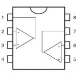
tl072


Categories
Blog Electronics

AVR cheap bass drum synthesis

The idea with the drum synth is to get a wide range of sounds out of the smallest, simplest possible circuit. There are 4 drum modes, bass, snare, hat and something more glitchy. I’m using an AtTiny45 as it’s got analogue inputs, fast PWM for output and enough memory for a few lookup tables of data. Here’s the test circuit:

The AtTiny chip is computing each sample at roughly 31kHz so I need to avoid any CPU-hungry operations like multiplication (8Mhz clock/31.25kHz = 256 instructions max). The bass drum gets around this by using two 8 bit lookup tables, each 256 bytes in size. The first is an ‘impact’ table which is a sort of exponential drop off curve and the second is a sine wave scaled to a 0-255 range. Source code is here (Compiled in g++, fuses L = 0xE2, H = 0xDF, E = 0xFF) and here’s the bit that does the important work:

impactPos += speed;
sinePos += pgm_read_byte(&impact_tbl[(impactPos >> 8) & 0xff]);
sample = pgm_read_byte(&sine_tbl[(sinePos >> 4) & 0xff]);

The sine table is being modulated by the ever-decreasing impact table so the frequency drops over time. The speed of the playback determines the pitch of the drum and the initial impactPos determines the type of sound. For a cheesy 70’s disco tom you set it to zero to go from a really high tone down to a low one. For a tech bass you start further down the curve to get a more muted and constrained sound.

This is a lazy approach as there is no decay on the volume – instead it depends on the drum playing out until the frequency of the sine wave is too low to hear. This avoids any multiplications but has some 8 bit artefacts as a consequence (I kind of like them).  Here’s some example output:

[audio:http://www.alexallmont.com/wp-content/uploads/2012/04/AttinyBassDrumTest.mp3|titles=AtTiny Bass Drum Test]
Categories
Blog Electronics

AVR filtered noise

A cheap LSFR gives a simple white noise output:

//--------------------------------------------------------------------------------
// Fast pseudo random number generator from
// http://en.wikipedia.org/wiki/Linear_feedback_shift_register
//--------------------------------------------------------------------------------
uint16_t g_rand = 0xACE1u;
void nextRand()
{
  g_rand = (g_rand >> 1) ^ (-(g_rand & 1u) & 0xB400u);
}

I want the effect of  filter sweeping this but being a little 8 bit chip, proper DSP is out of my league. Instead I do a cheap low pass filter by averaging the last sample with the current one, then the previous one to that with its previous etc.  To get more variation I average every other one and then fill the gaps, generates a sort of noise drop off curve:

#define FILTER_NOISE(idx1, idx2)    g_noise[idx1] = (g_noise[idx1] >> 1) + (g_noise[idx2] >> 1);
#define AVG_NOISE(idx1, idx2, idx3) g_noise[idx1] = (g_noise[idx2] >> 1) + (g_noise[idx3] >> 1);
 
uint8_t g_noise[16];
void updateNoise()
{
  nextRand();
  g_noise[0] = (uint8_t)g_rand; // ** Initial white noise value
  FILTER_NOISE(2, 0)    // Average every other sample to
  FILTER_NOISE(4, 2)    // get more muffled low pass white
  FILTER_NOISE(6, 4)    // noise.
  FILTER_NOISE(8, 6)
  FILTER_NOISE(10, 8)
  FILTER_NOISE(12, 10)  // Last couple of sample are filtering
  FILTER_NOISE(13, 12)  // each sample.
  FILTER_NOISE(14, 13)
  FILTER_NOISE(15, 14)
  AVG_NOISE(1, 0, 2)    // Averate between gaps in filtered
  AVG_NOISE(3, 2, 4)    // samples.
  AVG_NOISE(5, 4, 6)
  AVG_NOISE(7, 6, 8)
  AVG_NOISE(9, 8, 10)
  AVG_NOISE(11, 10, 12)
}

Messy code, but still faster than my awful assembly code version… beaten by GCC’s optimiser once again.  Here’s what it sounds like sweeping over this with a pot:

[audio:http://www.alexallmont.com/wp-content/uploads/2012/04/noise-capture.mp3|titles=noise capture]
Categories
Blog Electronics

Drum synth fast PWM

An update whilst getting the drum synth code together. The output is 8 bit at 31.25kHz, a frequency derived from the 8Mhz clock speed divided by 256 – the number of clock cycles it takes for the PWM ramp to go full cycle.

Interrupt initialisation including analogue input for potentiometers and piezo:

int main(void)
{
  // PWM output on PORTB0 = pin 5.
  DDRB = _BV(0);
 
  // PWM init, 8Mhz / 256 gives 31.25kHz
  TCCR0A =
    _BV(COM0A1) |           // Clear OC0A/OC0B on Compare Match.
    _BV(WGM00) |_BV(WGM01); // Fast PWM, top 0xff, update OCR at bottom.
  TCCR0B = _BV(CS00);       // No prescaling, full 8MHz operation.
  TIMSK = _BV(OCIE0A);      // Timer/Counter0 Output Compare Match A Interrupt Enable
 
  // Analogue init.
  ADCSRA |=
    _BV(ADEN) |              // ADC Enable
    _BV(ADPS1) | _BV(ADPS0); // Div 8 prescaler
 
  // Enable interrupts.
  sei();
 
  // Main loop.
  for (;;)
  {
    // ** Get user input **
  }
}

ISR sample update code, the sample is set as the PWM output, the sample update code sets it for the next time around:

uint8_t g_sample = 0;
ISR(TIM0_COMPA_vect)
{
  // 8 bit playback at 31.25kHz.
  OCR0A = g_sample;
  // ** Sample update code here **
}

Not the most cutting edge audio player, 8 bit and no fast buffering of any kind but good enough for now.  The sample generation code is tricker than expected; using an ATTINY45 means that efficient multiplication is not an option I’m in bit-hacking domain.

Categories
Blog Electronics

First Drum Synth Build

The drum runs from 5v but for project completeness sake I put it in a box with a 9v battery. The leftmost two pots control sound parameters with the third controlling volume. The piezo picks up finger impacts from the outside so you can play the drum by tapping the tin. From left to right the circuit goes: 9v to 5v regulator, ATTINY45 synth (with a header around chip for in-circuit programming), filtering & pre-amp, power amp.

Circuits always seem to end up denser when I actually build them – it was a cram getting all this onto protoboard.  The actual circuit is pretty neat but the rats’ nest of cables is from hooking everything up to switches.  I also had to shoehorn more caps in than expected.  It would have been wiser to choose a bigger box and measure/mark out all the controls rather than faff around with files and a hole-borer, but I  learned a lot for the next build in the process.  Notably: I’ve never experienced dry solder joints before but the analogue stage of this circuit really highlighted them, I’m used to using strip board and not this sort of protoboard so I need a bit of practice here; the piezo does all manner of weird stuff when the metal side is against the inside of the tin, grounding issues; the whole circuit could be shuffled to the right – squeezing the battery in was a relatively last-minute decision.

Paint job required. I’m still running this with the original software from my rhythm piano and I want to add more range to the sounds. The next post will have the first ‘official’ code release in which I’d like to include some lovely abrasive glitchcore modes I discovered whilst this circuit was playing up.

Categories
Blog Electronics

AVR Drum Synth Improvements

There were some immediate problems to address in my first draft of the drum circuit and fuelled by some Easter feedin’ I sat down to trawl through them.  Here’s the reworked schematic:

Summary of changes:

  1. The resistors on the output of the ATTINY45 have been tweaked to give a broader output PWM of around 1.6v to 5v
  2. These saturate the first unity gain op amp to generate a PWM signal with a range of 1.6v to 4.3v.
  3. The resistor after the low pass filter is much bigger, 1M so it doesn’t load the filter and screw up the signal.
  4. The second op amp gain is fixed at -0.5 (inverting 470k/1M).  This gives a nice clean signal for the transistor.
  5. The level adjust is now just a linear pot over the second op amp output.

Because the output level adjust pulls down to ground, a reduced signal is much lower so the transistors draw less current.  Now the Instead of always draining a constant 80mA the circuit now drains 20mA at low volume up to 80mA for absolute max.

First draft of this circuit in progress:

The rightmost pot is the level control for the drum – the leftmost two are parameters which will plug into the ATTINY45.  The leftmost switch is the power, the middle one select output on the amplifier or direct from the TL072 (not quite sure how to wire this up yet), the final switch selects whether the output is stereo/mono.

Categories
Blog Electronics

AVR Drum Synth Redesign

A few weeks ago I improvised a circuit to make drum sounds for my rhythm piano that I showed at BEAM Day at Brunel University.  Coding the synth was fun but getting the analogue electronics working was a baptism of fire; there was all sorts of system noise and I hastily threw in a low pass filter using totally the wrong component values… turns out most of my circuit was turning battery power into heat.

I’d like to use more of these synths so I’m redesigning it to be more efficient and will release the code in the aim of sharing and learning.  The circuit is designed as a hodgepodge of beginner electronics and guesswork, so there will be mistakes.  Here’s what I’ve got so far:

  1. Using fast PMW on the AVR Tiny45 gives 8 bit at approximately 40kHz.  I’m using the chip’s internal 8Mhz RC resonator as a clock.  For now the chip just sends out a constant sine wave for diagnostics.  The final version has two pots controlling sound parameters and a piezo input as the drum trigger.  The output PWM is 0-5v.
  2. Potential divider converts the 0-5v range to 2.5-5v.  This preps the signal for the first op amp where it saturates the buffer; using the full 0-5v range does funny things to the TL072 – it seems to stay at 5v with little spike signals.
  3. One half of the TL072 is used to buffer the signal, the voltage saturates the op amp giving an output of 1.5-4.5v PWM signal.
  4. A low pass filter converts the PWM signal into an analogue signal.
  5. The analogue signal is biased and levelled for the power stage.
  6. A push-pull power stage boosts the signal so it’s powerful enough for the headphones.  This sits at around 1v, which I think makes this a class A amplifier; minimal distortion but a bit power hungry.  This is the part of the circuit which needs reviewing.
Looking at my notes here, I think I’ve made an error with the 2.5-5v divider at stage (2) – the values should be different.  I’ll check this before the next post where I build the circuit and test the drums.
The circuit in action.  Yellow scope is filtered signal, red scope is output from power stage.  Presently the whole circuit soaks around 80mA.